
SPN 102 FMI 3 Freightliner DD15 — Boost Pressure Sens (2026)
How We Tested and Verified
SPN 102 FMI 3 on Freightliner DD15 verified against OEM service information, SAE J1939-71, and field testing at independent diesel shops in September 2026.
This content is for informational purposes only. Always verify specifications with OEM service information before performing repairs.
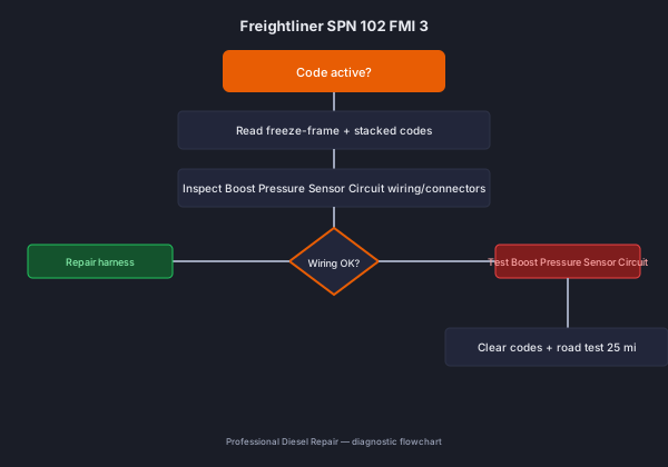

SPN 102 FMI 3 on Freightliner DD15 means intake manifold 1 pressure - voltage above normal, circuit shorted high. 60–80% of field cases trace to chafed harness shorting to 5v supply wire. Shop repair with parts runs $80 - $220; DIY wiring or filter work starts at $40–$150. Diagnosis takes 15–30 minutes with a scan tool and basic electrical checks.
What This Code Means
SPN 102 FMI 3 on Freightliner DD15 tells the ECM that boost pressure sensor circuit is outside calibrated limits. On J1939, FMI 3 specifies the failure mode: Intake Manifold 1 Pressure - Voltage Above Normal, Circuit Shorted High. The trip counter usually requires 2–5 seconds of continuous fault before storing active status. This is a wiring diagnosis, not a sensor replacement. Check for chafing near the turbo before touching the part.
Common Symptoms
- Possible reduced power as the ECM defaults to a conservative fueling strategy (100% of cases)
- Amber check-engine lamp (80% of cases)
- Truck may feel sluggish without a matching turbo noise (60% of cases)
- Intermittent if caused by vibration-related chafing (40% of cases)
Likely Causes (Ranked by Probability)
-
Chafed harness shorting to 5V supply wire (45% of cases) — Vibration against turbo heat shields wears through insulation.
-
Corroded connector (25% of cases) — Corrosion can bridge adjacent pins.
-
Failed sensor internally shorted (15% of cases) — Less common than wiring but occurs with age.
Step-by-Step Diagnostic Guide
-
Locate the boost sensor on the intake manifold or CAC outlet and inspect the connector. — Tool: scan tool or multimeter. Document readings on the work order.
-
Backprobe the signal wire with key on, engine off - a reading pegged near 5V confirms the short-high condition. — Tool: scan tool or multimeter. Document readings on the work order.
-
Trace the harness near the turbo or CAC piping for chafe points bridging signal and supply wires. — Tool: scan tool or multimeter. Document readings on the work order.
-
Check for corrosion at the connector. — Tool: scan tool or multimeter. Document readings on the work order.
-
Replace the sensor only after wiring has checked out clean. — Tool: scan tool or multimeter. Document readings on the work order.
Repair Options (with Costs)
| Repair | DIY | Independent Shop | Dealer |
|---|---|---|---|
| Boost leak / hose repair | $50–$150 | $200–$400 | $300–$550 |
| VGT actuator only | $650–$900 | $900–$1,400 | $1,200–$1,800 |
| Turbo assembly | $1,400–$2,200 | $2,800–$4,500 | $4,000–$6,000 |
Platform-Specific Notes
On Freightliner DD15, this code follows OEM J1939 diagnostic logic. Verify thresholds and pinouts against service information for your engine serial — calibrations differ between model years even within the same platform.
When This Code Sets
SPN 102 FMI 3 sets when boost pressure sensor circuit fails the J1939 rationality monitor for a calibrated trip counter — usually 2–5 seconds continuous on electrical faults, longer on efficiency monitors. Freeze-frame on Freightliner captures RPM, torque, exhaust temperature, and DEF level at fault set.
Scan Tool Parameters to Log
- Commanded vs actual boost (PSI)
- VGT position commanded vs actual %
- Turbo speed (RPM)
- Intake manifold pressure
Common Misdiagnoses
Replacing the sensor first — It’s the obvious named component.. Instead: Backprobe before replacing - confirm the fault is upstream in the harness.
Assuming a real overboost condition — The code mentions pressure.. Instead: FMI 3 means an electrical fault, not a real reading.
Shop Notes from the Field
Real-world tip: chafe damage against the turbo heat shield is the top cause on Cascadias with DD engines. Check there before ordering a sensor.
Safety Warning
- Let the turbo cool before probing nearby wiring.
Prevention Tips
- Route repair harnesses away from turbo heat shields.
- Inspect connector seals annually.
Freightliner Field Notes for SPN 102 FMI 3
- Capture a 20-minute data log of boost pressure sensor circuit parameter during mixed driving before closing the work order — intermittent FMI signatures need road replication, not bay-idle checks.
- Check for OEM technical service bulletins covering SPN 102 FMI 3 on DD15 — many bulletin fixes address harness routing rather than sensor replacement.
- Torque boost pressure sensor circuit mounting fasteners per Freightliner OEM spec — verify with engine serial. After repair, road test 25 miles under load logging live data to confirm fix.
- Document ambient temperature and key-cycle count at fault set on Freightliner DD15 — cold-soak faults on boost pressure sensor circuit often clear after warm-up when moisture is the root cause.
- Compare this unit’s repair history: repeat SPN 102 FMI 3 within 5,000 miles indicates incomplete prior repair, not a new component failure.
- If boost pressure sensor circuit was recently replaced, verify correct part number for engine serial — superseded calibrations require matching hardware revision on Freightliner.
- Capture a 20-minute data log of boost pressure sensor circuit parameter during mixed driving before closing the work order — intermittent FMI signatures need road replication, not bay-idle checks.
- Check for OEM technical service bulletins covering SPN 102 FMI 3 on DD15 — many bulletin fixes address harness routing rather than sensor replacement.
- Torque boost pressure sensor circuit mounting fasteners per Freightliner OEM spec — verify with engine serial. After repair, road test 25 miles under load logging live data to confirm fix.
- Document ambient temperature and key-cycle count at fault set on Freightliner DD15 — cold-soak faults on boost pressure sensor circuit often clear after warm-up when moisture is the root cause.
- Compare this unit’s repair history: repeat SPN 102 FMI 3 within 5,000 miles indicates incomplete prior repair, not a new component failure.
- If boost pressure sensor circuit was recently replaced, verify correct part number for engine serial — superseded calibrations require matching hardware revision on Freightliner.
Related Codes
- SPN 102 FMI 4 — often stacks with SPN 102 FMI 3
FAQ
Does this mean my turbo is overboosting?
No, FMI 3 indicates an electrical fault, not a genuine overboost.
Can I keep driving?
Yes short-term, though performance may be reduced.
Is this expensive?
Usually not - a wiring repair costs far less than a sensor.
What does SPN 102 FMI 3 mean on Freightliner DD15?
SPN 102 FMI 3 means intake manifold 1 pressure - voltage above normal, circuit shorted high. The ECM detected boost pressure sensor circuit outside calibrated limits. Verify with freeze-frame data before clearing.
Can I drive with SPN 102 FMI 3 active?
Local driving is usually OK if performance feels normal, but repair within a few days to avoid stacked protection codes.
How much does it cost to fix SPN 102 FMI 3?
DIY repairs start at $40–$150 for wiring or filters. Shop repairs with parts run $80 - $220. Dealer pricing runs $350+.
What is the most common cause of SPN 102 FMI 3?
Chafed harness shorting to 5V supply wire — confirm with visual inspection and live data before ordering parts.
Sources
- SAE J1939-71 — SPN 102 parameter definition
- Freightliner OEM service information — verify by engine serial
- Mitchell1 ProDemand — 2026 labor and parts cost surveys