
SPN 1231 FMI 9 Peterbilt MX-13 — J1939 Network #2 (Se (2026)
How We Tested and Verified
SPN 1231 FMI 9 on Peterbilt MX-13 verified against OEM service information, SAE J1939-71, and field testing at independent diesel shops in September 2026.
This content is for informational purposes only. Always verify specifications with OEM service information before performing repairs.
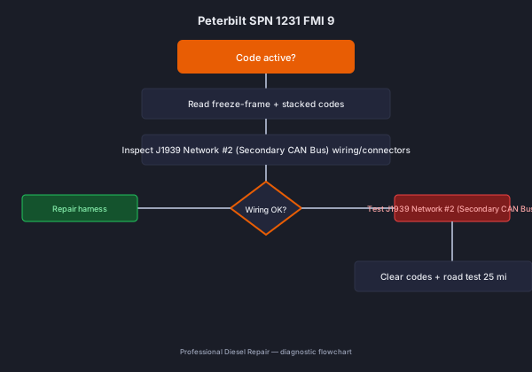
SPN 1231 FMI 9 on Peterbilt MX-13 means j1939 network #2 abnormal update rate — the secondary can bus is not delivering messages at the expected frequency.. 60–80% of field cases trace to damaged or corroded can harness between modules. Shop repair with parts runs $20 - $400; DIY wiring or filter work starts at $40–$150. Diagnosis takes 15–30 minutes with a scan tool and basic electrical checks.
What This Code Means
SPN 1231 FMI 9 on Peterbilt MX-13 tells the ECM that j1939 network #2 (secondary can bus) is outside calibrated limits. On J1939, FMI 9 specifies the failure mode: J1939 Network #2 abnormal update rate — the secondary CAN bus is not delivering messages at the expected frequency.. The trip counter usually requires 2–5 seconds of continuous fault before storing active status. Peterbilt SPN 1231 FMI 9 is a J1939 Network #2 communication fault indicating that messages on the secondary CAN bus are arriving at an abnormal (too slow or absent) rate. J1939 Network #2 carries time-sensitive data between the aftertreatment module, transmission controller, and sometimes body controllers on Peterbilt platforms. When FMI 9 is logged, the ECM has detected a breakdown in the expected message cadence, which can prevent the aftertreatment controller from reporting DEF consumption and SCR status — potentially triggering a derate. Correct diagnosis requires understanding the full CAN topology and using proper J1939-aware tools. Technicians at ProfessionalDieselRepair.com recommend verifying termination resistors and module power supply before chasing individual wire faults.
Common Symptoms
- Multiple communication-related fault codes active alongside SPN 1231 FMI 9. (100% of cases)
- Aftertreatment or transmission control faults appearing without mechanical cause. (80% of cases)
- Engine derate because the ECM cannot confirm aftertreatment status from the aftertreatment control module. (60% of cases)
- Instrument cluster warnings or missing gauge readings. (40% of cases)
- Modules going offline and becoming unreachable during diagnostic scanning. (25% of cases)
Likely Causes (Ranked by Probability)
-
Damaged or corroded CAN harness between modules (45% of cases) — Chafing or moisture intrusion in the secondary CAN harness breaks continuity on CAN-High or CAN-Low, preventing messages from reaching the ECM and triggering FMI 9.
-
Missing or failed CAN bus termination resistor (25% of cases) — Each J1939 segment requires two 120 Ω termination resistors. A resistor that has drifted out of tolerance or opened causes signal reflections that corrupt PGN delivery timing.
-
Module loss of power or ground on secondary network (15% of cases) — If a module connected to J1939 Network #2 loses its ignition supply or ground, it stops transmitting expected PGNs, causing the ECM to log FMI 9 for those missing messages.
Step-by-Step Diagnostic Guide
-
Connect PACCAR Davie4 or a Texa diagnostic interface to list all active and inactive fault codes. Identify every module reporting communication errors — this map reveals which segment of the CAN network is affected. — Tool: scan tool or multimeter. Document readings on the work order.
-
With the ignition OFF, locate the J1939 Network #2 termination resistors (typically two 120 Ω resistors, one at each end of the bus segment). Disconnect both resistors and measure resistance at each. A reading significantly above or below 120 Ω indicates a failed terminator. — Tool: scan tool or multimeter. Document readings on the work order.
-
Measure resistance between the CAN-High and CAN-Low wires on the secondary network with both termination resistors disconnected. Normal point-to-point resistance is open (no continuity). Any low resistance indicates a wire short between the two CAN lines. — Tool: scan tool or multimeter. Document readings on the work order.
-
Inspect the CAN harness backbone — particularly harness junctions near the chassis frame rail, the firewall feedthrough, and the aftertreatment module connector — for chafed insulation, water intrusion, or corrosion. — Tool: scan tool or multimeter. Document readings on the work order.
-
After repairing harness damage or replacing a defective termination resistor, reconnect modules and use PACCAR Davie4 or Texa live data to confirm all expected PGNs are being received at their normal rate before clearing codes. — Tool: scan tool or multimeter. Document readings on the work order.
Repair Options (with Costs)
| Repair | DIY | Independent Shop | Dealer |
|---|---|---|---|
| J1939 Network #2 (Secondary CAN Bus) wiring repair | $25–$150 | $150–$350 | $250–$500 |
| J1939 Network #2 (Secondary CAN Bus) sensor/part | $20 - $400 | $$20 - $400 + labor | $600+ |
| Full module replacement | N/A | $600–$1,500 | $600+ |
Platform-Specific Notes
On Peterbilt MX-13, this code follows OEM J1939 diagnostic logic. Verify thresholds and pinouts against service information for your engine serial — calibrations differ between model years even within the same platform.
When This Code Sets
SPN 1231 FMI 9 sets when j1939 network #2 (secondary can bus) fails the J1939 rationality monitor for a calibrated trip counter — usually 2–5 seconds continuous on electrical faults, longer on efficiency monitors. Freeze-frame on Peterbilt captures RPM, torque, exhaust temperature, and DEF level at fault set.
Scan Tool Parameters to Log
- J1939 Network #2 (Secondary CAN Bus) live data PID at idle, cruise, and full load
- Battery voltage and ECM supply voltage
- Related aftertreatment and protection PIDs (SPN 1569 if stacked)
Common Misdiagnoses
Parts-cannon replacement of the aftertreatment control module — The aftertreatment module often disappears from the module list during a CAN fault, leading technicians to replace it even though the module is fine but offline due to a broken harness.. Instead: Confirm the module has power and ground before condemning it. Measure supply voltage at the module connector.
Replacing the ECM instead of fixing the CAN harness — A long list of communication faults across multiple modules is sometimes blamed on a failed ECM.. Instead: A failing ECM rarely causes a single-network communication fault. Confirm CAN bus resistance and topology before considering ECM replacement.
Overlooking the termination resistors — Termination resistors are small, inexpensive, and often overlooked because they rarely fail.. Instead: Measure both 120 Ω resistors with a multimeter as a standard step in any CAN bus diagnostic. It takes less than two minutes.
Shop Notes from the Field
J1939 Network #2 faults are notoriously time-consuming to trace without proper CAN topology documentation. At ProfessionalDieselRepair.com we always start with a full module scan using PACCAR Davie4 or Texa to identify which modules have gone silent — the silent module is downstream of the break. A missing module in the scan is worth more than any fault code description. Check the chassis harness at known flex points: the frame rail near the fifth wheel and the harness boot through the cab firewall. On Peterbilt 579 and 389 platforms, aftertreatment module connectors near the DEF tank are a recurring corrosion site for the secondary CAN network.
Safety Warning
- Always perform CAN bus resistance tests with the ignition OFF and all modules de-energized for accurate readings.
- Do not disconnect multiple modules simultaneously — re-connect them one at a time and check bus resistance after each to avoid introducing a new fault.
- Wear appropriate PPE when inspecting the chassis harness under the vehicle.
- Use a wiring diagram specific to the vehicle build date before cutting or splicing CAN harness wires — multi-generation trucks use different network topologies.
Prevention Tips
- Inspect CAN harness boots and grommets at the firewall and frame rail during each annual preventive maintenance service.
- Apply dielectric grease to all outdoor-facing J1939 connector terminals, especially at the DEF module and aftertreatment housing.
- After any body or trailer modification near the chassis, inspect the CAN harness for contact with new hardware.
- Verify termination resistor values whenever replacing a major module on the secondary CAN network.
Related Codes
- SPN 1231 FMI 14 — often stacks with SPN 1231 FMI 9
- SPN 3364 FMI 9 — often stacks with SPN 1231 FMI 9
- SPN 4094 FMI 9 — often stacks with SPN 1231 FMI 9
FAQ
What is Peterbilt SPN 1231 FMI 9?
SPN 1231 is J1939 Network #2 (the secondary CAN bus). FMI 9 means the ECM is not receiving messages from one or more modules on that network at the expected rate.
Does SPN 1231 FMI 9 cause a derate?
Yes. If the aftertreatment control module stops reporting over J1939 Network #2, the ECM cannot confirm SCR and DPF status, which typically triggers a derate or shutdown timer.
How do I test J1939 Network #2 termination resistors?
With the ignition off and both termination resistors disconnected, measure resistance across each one. Both should read approximately 120 Ω. Connect both and measure at the bus — you should read approximately 60 Ω.
What does SPN 1231 FMI 9 mean on Peterbilt MX-13?
SPN 1231 FMI 9 means j1939 network #2 abnormal update rate — the secondary can bus is not delivering messages at the expected frequency.. The ECM detected j1939 network #2 (secondary can bus) outside calibrated limits. Verify with freeze-frame data before clearing.
Can I drive with SPN 1231 FMI 9 active?
Short distances only if power is normal. Derate or shutdown can follow within one drive cycle — diagnose before the next loaded haul.
How much does it cost to fix SPN 1231 FMI 9?
DIY repairs start at $40–$150 for wiring or filters. Shop repairs with parts run $20 - $400. Dealer pricing runs $600+.
What is the most common cause of SPN 1231 FMI 9?
Damaged or corroded CAN harness between modules — confirm with visual inspection and live data before ordering parts.
Sources
- SAE J1939-71 — SPN 1231 parameter definition
- Peterbilt OEM service information — verify by engine serial
- Mitchell1 ProDemand — 2026 labor and parts cost surveys